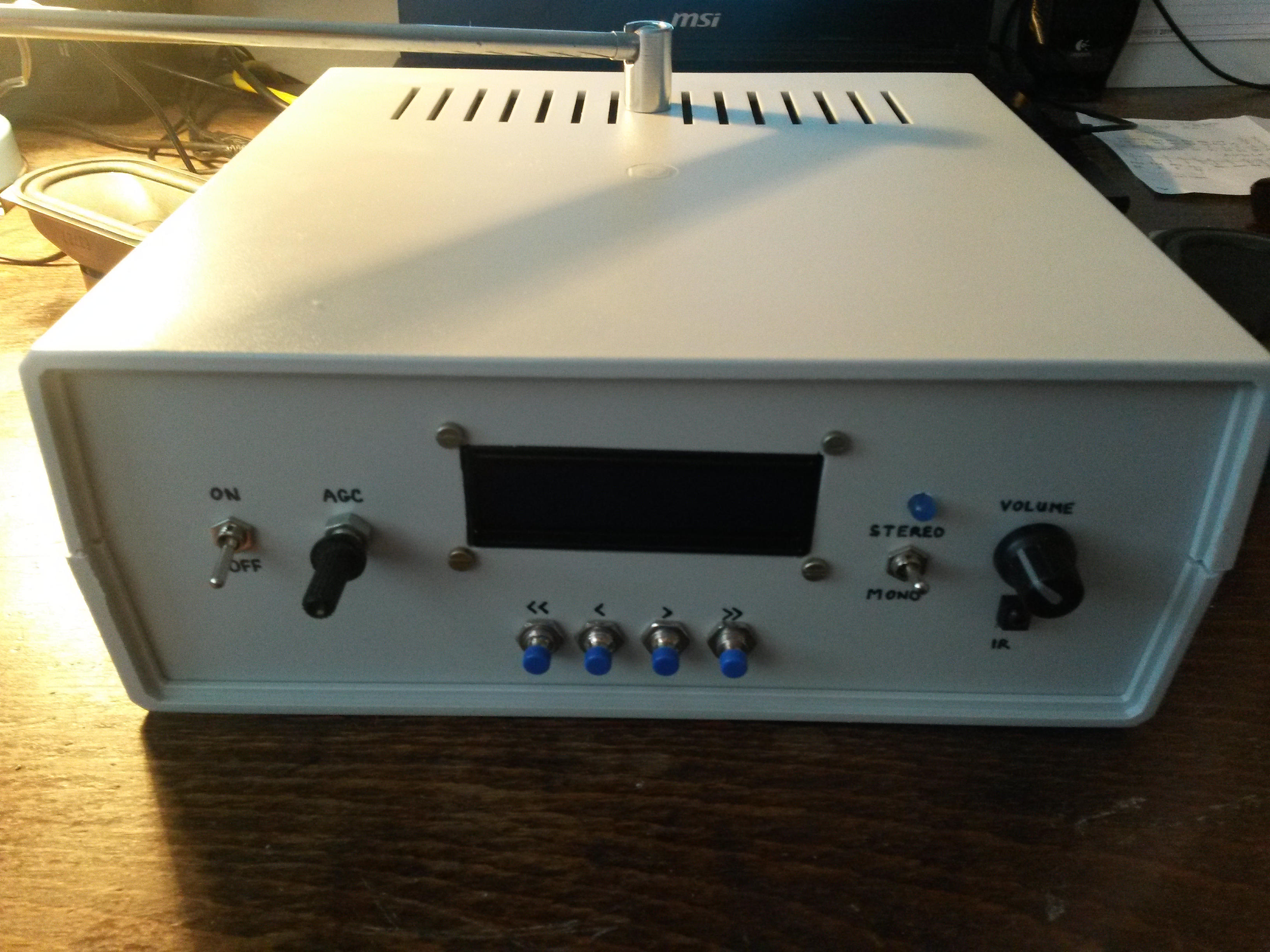
Stereo FM radio with RDS, digital tuning and remote control
The article starts below the video.
I assembled together all my knowledge about TV tuners, microcontroller programming, remote control and RDS, and resulting is this FM radio receiver.
- Architecture: superhet with double mixing
- Range: 87.5 - 108 MHz (can be easily enlarged to 48 - 863 Mhz, but there is no point in it)
- Power source: 12 V / 250 mA (without AF amplifier)
- Output: stereo for headphones or AF amplifier
- Tuning: digital (PLL), in steps +-50 kHz, +- 500 kHz
- 10 programmable frequencies
- Manual AGC
- Mono/stereo switch, Mute function
- Remote control with any remote
- RS232 output with RDS data
The schematic is a little more complicated, but there are some apparent building blocks which are described later.
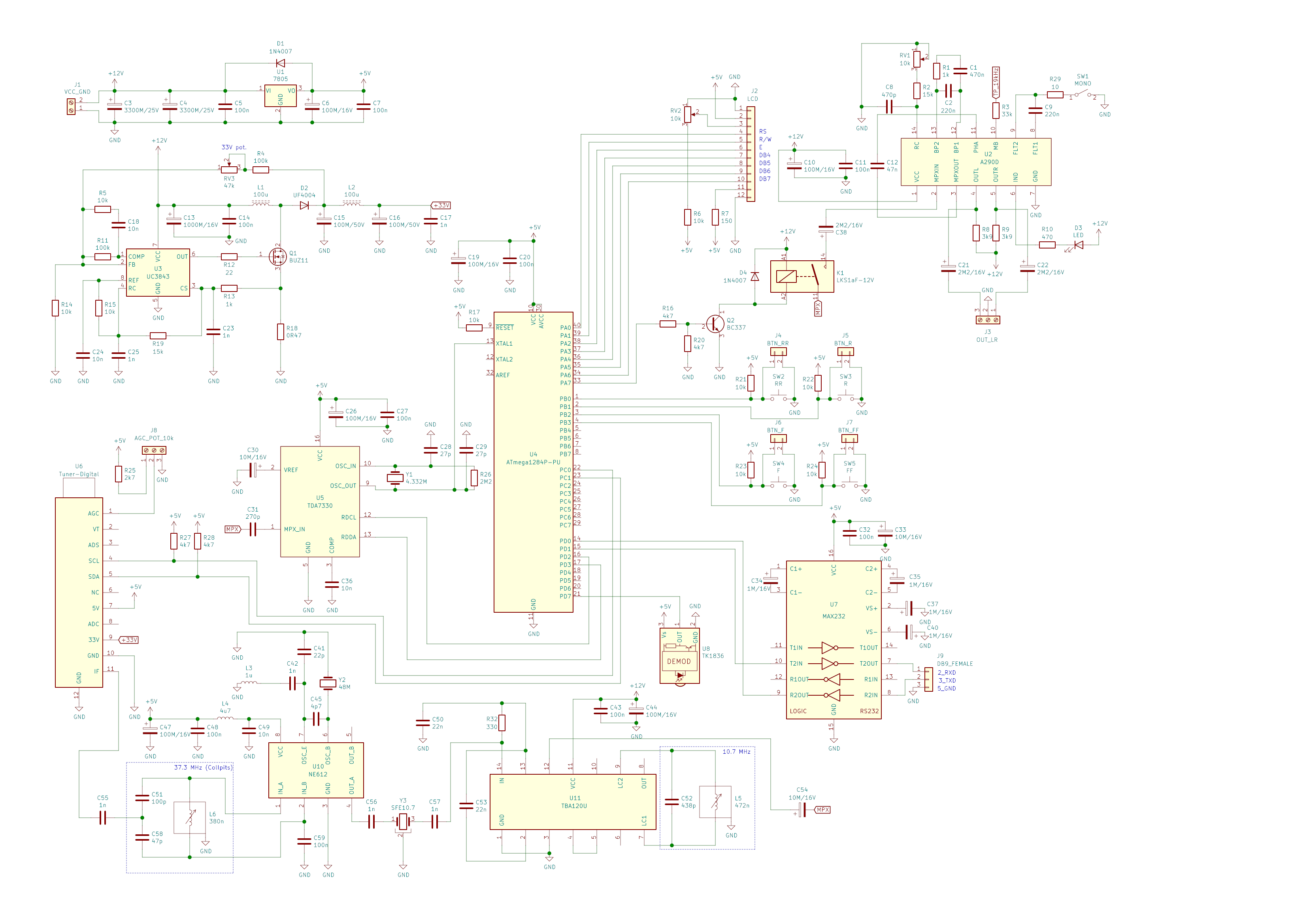
Used is a tuner with digital tuning (PLL) and it is controlled by I2C bus - pins SDA and SCL. More information about these tuners can be found in my older article. For this construction, suitable tuners are PLL tuners with asymmetrical output. I have tried and confirmed the following types are working:
- KS-H-148EA
- KS-H-148EAS
- KS-H-144EA
- UV1316
- ENV57DA0G3D
- QINGJIA AFT0/1010G 3200 1559
The first three are often found in CRT TVs Orava (OVP, OTF). They are functionally equivalent to UV1316 and detailed datasheets can be found on the internet by their type.
AGC is manual, must be in the 0 - 4 V range, and so there is a potentiometer connected via a resistor to 5 V. Some stations are best received with AGC roughly in the middle, other stations with full AGC.
5 V voltage is made using a 7805 voltage stabilizer in a datasheet-like connection. It's OK without a heatsink, but it heats up considerably, so I made some space for a small heatsink on the PCB.
33 V voltage is made using a step-up DC converter with UC3843. This IC is also very frequently used in CRT TVs and monitors. Also the MOSFET in this DC converter can be found in these devices - for example IRF630 can be used instead of BUZ11. This MOSFET does not heat up at all and so there is no heatsink. There is an LC filter on the output to avoid noise. The output is nicely constant, I measured it with an oscilloscope. Output voltage is set up using the RV3 trimmer, it must be set to 33 V when first setting up. This DC converter is much better than MC34063 that I used in my older constructions, where it caused considerable noise that could not be prevented.
Processing IF signal from tuner
IF output from tuner has bandwidth 8 MHz, from 32 to 40 MHz. The next step is conversion from 37.3 MHz to 10.7 MHz (because 48 - 10.7 = 37.3). IC NE612 serves this purpose, it's a double balanced mixer and oscillator. Output is not balanced and so only pin 4 is used, pin 5 is left unconnected. On the input is included a Collpits circuit with a variable inductor and two ceramic capacitors, which, according to the datasheet, is good to suppress undesired mixing products. In the datasheet it is described as "Single-ended tuned input". Parameters of the LC circuit must be chosen in a way to tune on 37.3 MHz, which is the frequency we want to process. The LC circuit may be left out and the IF only dirty-connected via a 1 nF capacitor to pin 1 of NE612, but I have verified that with the LC circuit I get considerably better 10.7 MHz signal out of NE612.
Oscillator part of NE612 circuit contains a 48 MHz crystal which can be probably scavenged from old PC motherboards. This frequency is so-called "third overtone", and with L3 and C42 present, oscillation on base frequency is suppressed.
The signal is passed through the SFE10.7 filter to the FM demodulator TBA120U. Important - it must be the U version, using an S or T version would require more changes to the circuit. So-called "phasing LC circuit" on pins 7 and 9 is tuned to 10.7 MHz. AF output is on pin 8 (regulated) and pin 12 (unregulated). It is worth to note here that in the TBA120U datasheets and in my older constructions, there is a 15 nF "deemphasis" capacitor on the AF output to ground. I found out only by accident that without it stereo works and with it stereo does not work. Only later I found out that it behaved as a simple lowpass filter so stereo information (and RDS) were cut out.
Demodulated AF signal (so-called MPX signal containing also other components such as stereo, RDS and so on) is passed into the input of RDS decoder, but also via a relay into stereodecoder A290D. This IC is in datasheet-like circuit. By trimmer RV1, frequency 19 kHz is tuned in test point TP_19kHz. You can use a frequency counter for that, but easier way is doing that by listening and looking at the stereo indication LED, which should light up when a stereo broadcast is tuned in and the trimmer is in correct position.
Here the signal path on the board is ended. It can be further connected to headphones or an AF amplifier with speakers. I used a small module with TDA7266S that I constructed a longer time ago. This IC is also frequently found in old CRT TVs Orava and can be nicely re-used.
Digital part
Since the tuner is controlled by I2C, using a microcontroller in this construction could not be avoided. The I2C bus must be connected via pull-up resistors 4k7 to 5 V rail.
Now that we have a microcontroller, why not use it fully to add user-friendly functions?
First, the processing of RDS data - it is the purpose of TDA7330B. This IC can't be found in old electronic devices and must be bought e.g. from ebay because our local shops never heard of it. Same situation is with the 4.332 MHz crystal which is a specific frequency required by the RDS decoder IC. Clock from the crystal is also used as clock source for the microcontroller. Signals RDCL and RDDA are the outputs of the RDS decoder. RDCL is input to INT0 pin of microcontroller and in its program, interrupt is handled by reading a bit from RDDA.
Tuning is performed by four hardware buttons:
- F: +0,05 MHz
- R: -0,05 MHz
- FF: +0,5 MHz
- RR: -0,5 MHz
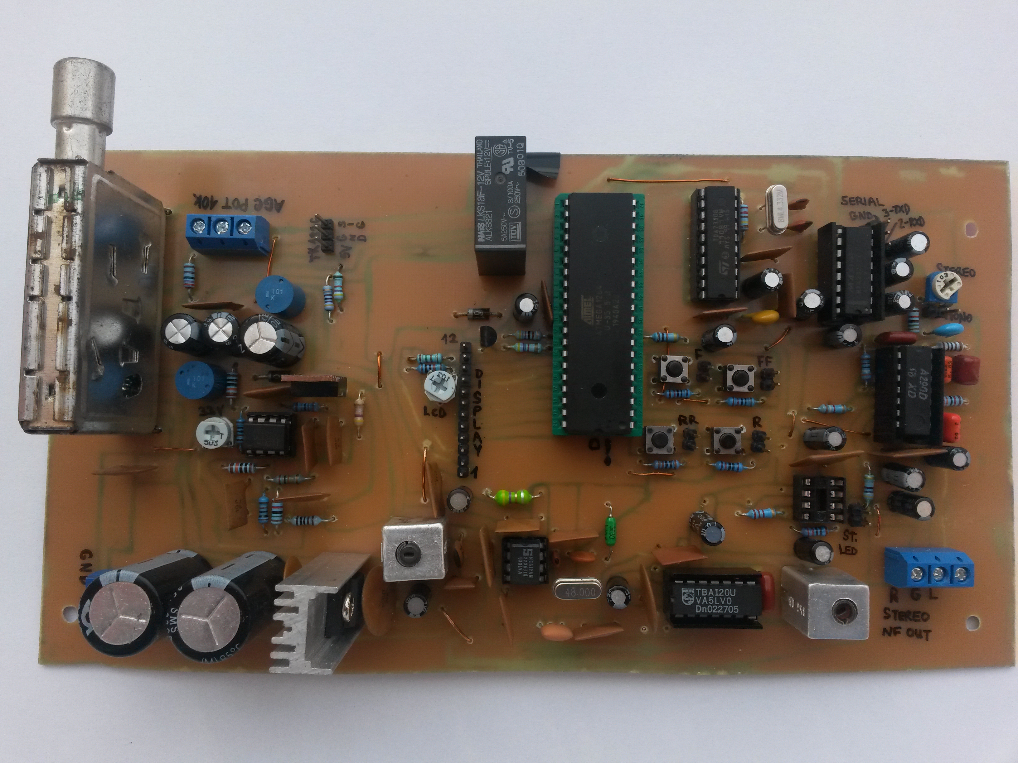
On the board, there are tactile buttons and pin headers next to them that can be used to connect front panel buttons.
Next is the relay controlled by a common NPN transistor. The relay connects and disconnects AF signal that goes into the stereodecoder. It is switched on with delay when the radio is turned on to avoid short noise when tuner is already on but microcontroller not yet (because tuner starts on some default frequency). Microcontroller remembers last used frequency in EEPROM and this frequency is tuned in immediately on microcontroller start. So when the relay turns on, everything is ready. The relay is also controlled by the Mute function which is only available via IR remote. Relay is present on the stereodecoder input and not output, so that just a single-pole relay can be used.
LCD display 16x2 is best used with a backlight. There is a 12-pin header on the board for its connection, and the meaning of each pin is described in the schematic. Connection of the LCD is fairly straightforward and datasheet-like. Contrast is regulated by the RV2 trimmer.
Infrared remote receiver is also pulled out from old CRT TV. I had various receivers at hand and decided to use TK1836, connection of which is also reflected in the pin header layout on the board. Of course, also TSOP1836 can be used, but that one could not be easily mounted on the panel as used ones normally have very short pins. Remote control is programmatically handled by the IRMP library which supports many protocols.
Integrated circuit MAX232 is connected to the RXD and TXD pins of the microcontroller. It's there because RXD and TXD are TTL only (5 V max), but RS232 requires higher levels, including positive and negative voltage. This is ensured by the MAX232 IC. Its output can be connected to a PC, for example via an USB-RS232 converter, since RS232 ports are no longer present on today's PC. If you want to spare some cash, you can leave out MAX232 and its associated components. RS232 is used to send RDS information to a PC for further analysis. There is much more information than is displayed on the LCD display, such as station PI code, alternative frequencies, current date/time, broadcast type...

User manual
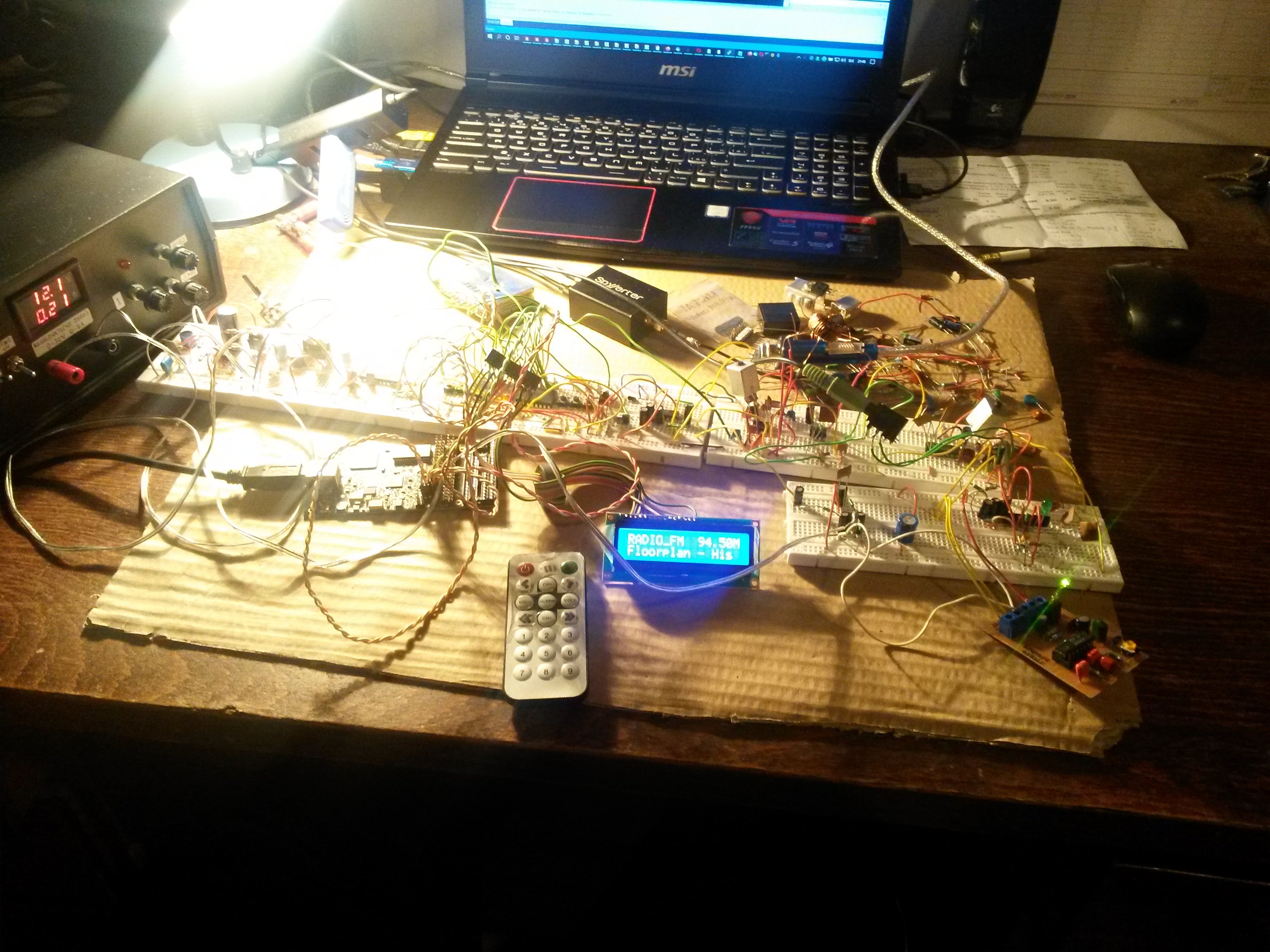
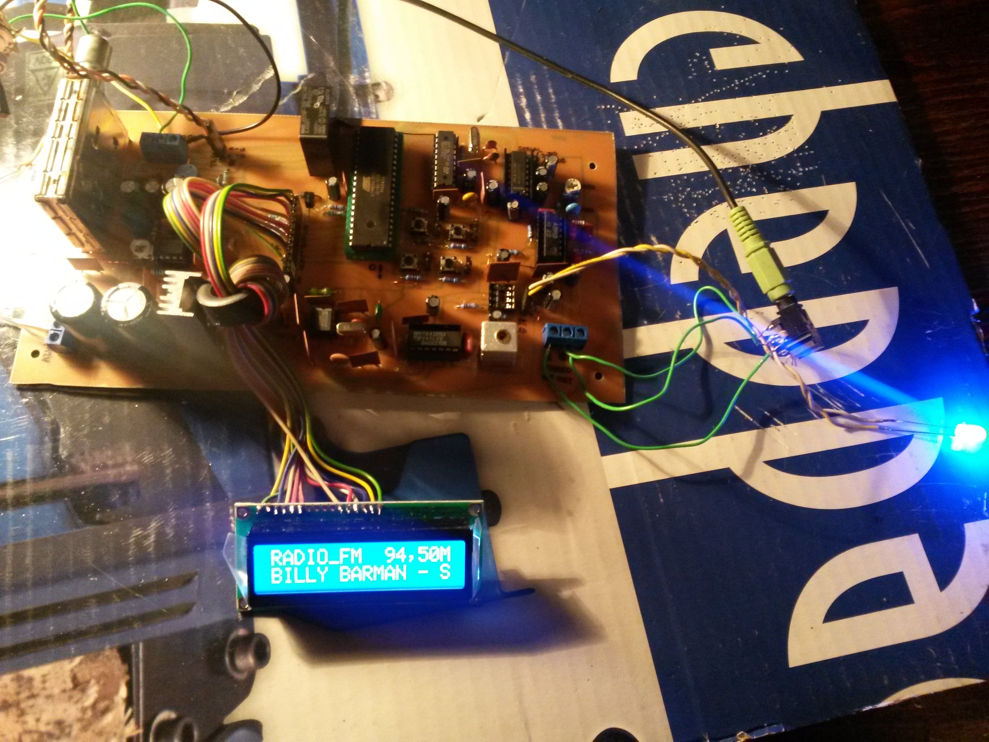
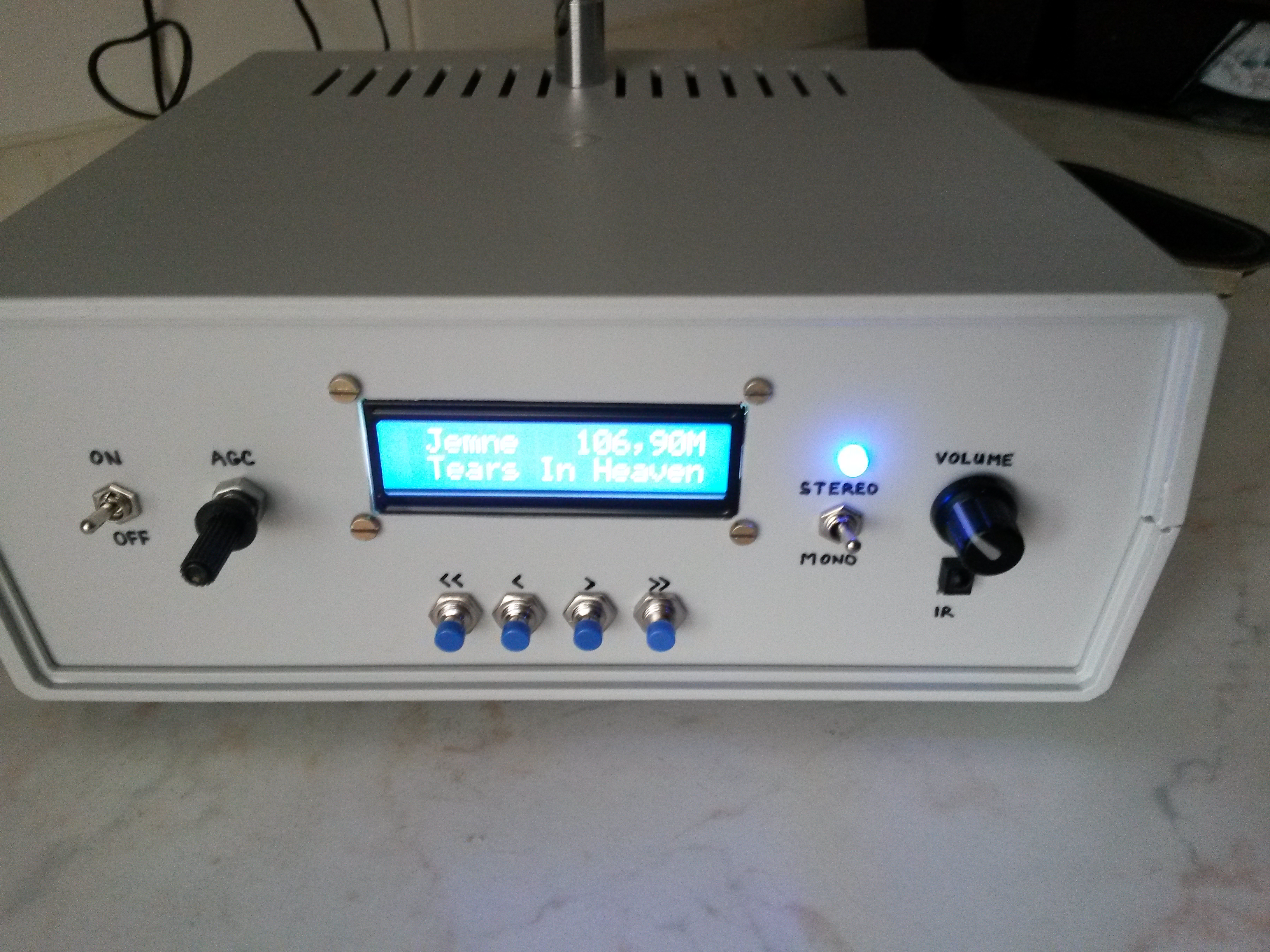
On power-up, display shows "FM Radio by Mek, www.mekweb.eu" and relay is turned on, which causes the radio to start playing last tuned-in frequency, or 87.5 MHz if turned on for the first time. Display shows station name, current frequency (such as 102.55M) and programme identification such as song name. Programme identification is usually longer than 16 characters, so it is slowly scrolled. If no RDS signal is present, "FM, no RDS" is shown.
How to learn the radio to use a specific infrared remote control? Simply you have to press buttons R and F at the same time. Display shows "Remote learning" and the radio requests IR remote codes for buttons:
- Program 1 - 10
- RR, R, F, FF
- Mute
- Remember program
In each step you have to press a button on the remote control that will be used to perform requested function. This setup only must be performed once, all settings are saved to EEPROM.
When you have all functions learnt, you can use your remote control to tune, use the Mute function, remember programs, and recall remembered programs.
After tuning a station, press button "Remember program" on remote control. Display then shows a request to press a button of program under which the currently tuned-in frequency will be saved. Press one of the buttons Program 1 - 10 and the frequency is saved. In the future, when you want to listen to the remembered station, just press the specific Program button on remote control. You can remember all 10 programs this way.
Notes for building the radio
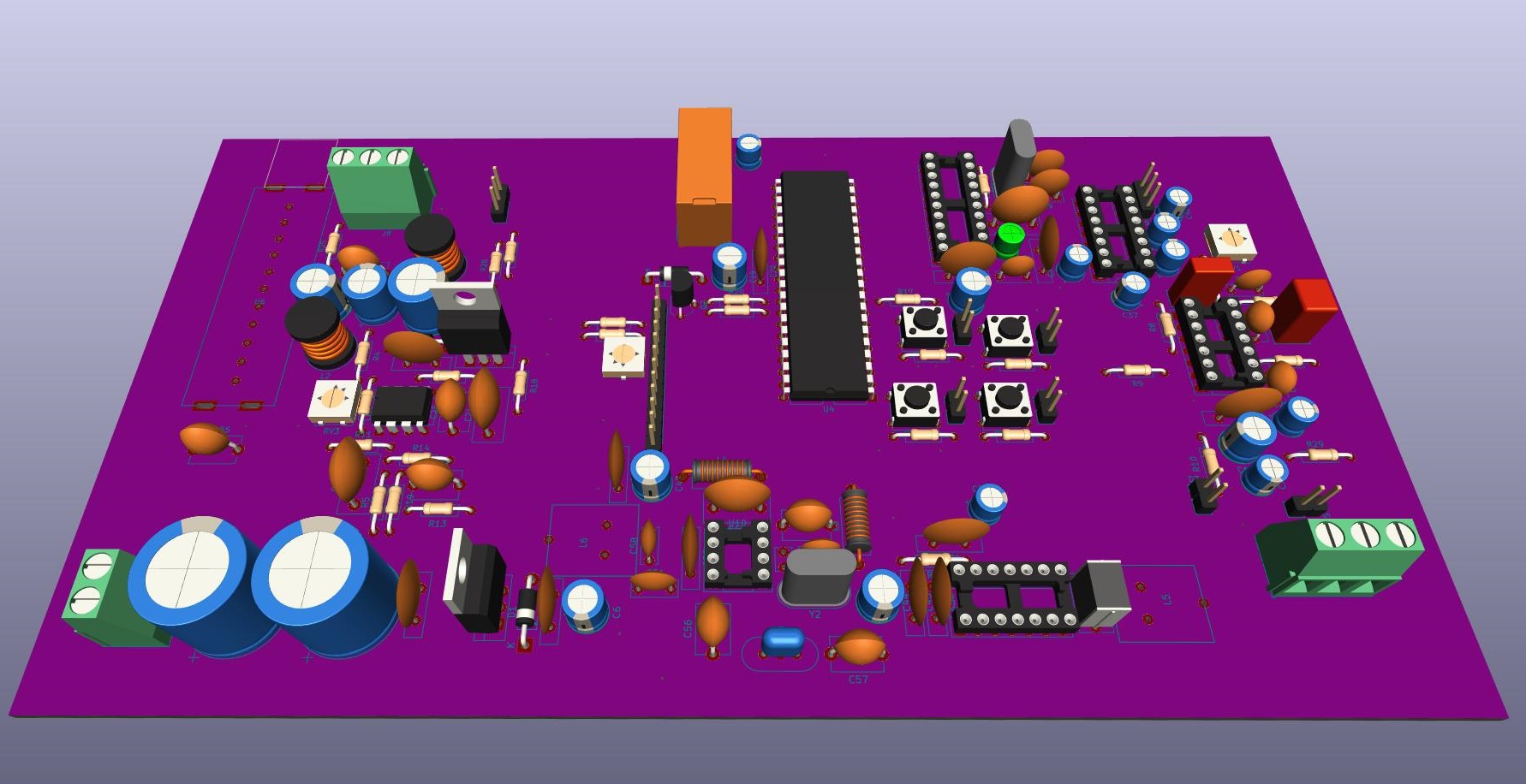
Attached to this article is a KiCad project with a schematic and PCB layout. Dimensions of the PCB are 20x11.5 cm. When bringing the radio to life, and most noticeably in case of problems, an USB SDR dongle for PC is very handy (including an up-converter if needed). This can be used to check tuner IF output in range 32-40 MHz, and second IF 10.7 MHz as well. For tuned LC circuits you will need a good LC meter, or maybe some pre-tuned LC pairs. Tuned inductors can be scavenged from old Tesla TVs, and PCB footprints count with exactly this scenario. To calculate LC resonance frequency, I recommend this page. And also I recommend an LCR meter such as DER EE DE-5000 which can measure inductance also in the nH range.
Some components can be replaced by other ones:
- NE612 = NE602 = SA612 = SA602
- TBA120U = A223D = K174UR4 (K174УP4)
- for example IRF630 instead of BUZ11
Beware - the steps of bringing the radio to life counts with starting situation that tuner is not soldered in yet, and DIP sockets are used everywhere instead of ICs. Use a stabilized power supply with current limiter - 12 V, 250 mA, and note that this current limit must never be reached (apart from initial capacitor charging).
- Turn on and check 12 V and 5 V on all pins of IO sockets according to the schematic
- Turn off
- Seat UC3843 in its socket
- Connect AGC potentiometer
- Turn on
- Check +33 V on pin 9 of (not yet connected) tuner. If it's not 33 V, use RV3 to set correct voltage
- Check voltages on other tuner pins: +5 V, AGC (variable from 0 to 4 V by turning the AGC potentiometer)
- Turn off
- Seat the microcontroller and connect LCD display
- Turn on
- By using RV2, set up display contrast so that only first row of rectangles is shown
- Turn off
- Seat TDA7330B in its socket (from this moment on, the microcontroller will also have clock source)
- Turn on
- Display should show initial message "FM Radio by Mek, www.mekweb.eu"
- Turn off
- Solder the tuner in its place
- Turn on
- Display should show the initial message, and shortly enter normal mode. Relay should be turned on. Display should show "FM, no RDS" and frequency 87.5M. If still only the initial message is shown, probably there is a problem with I2C communication between the microcontroller and tuner.
- Try tuning using the four buttons
- Connect IR receiver
- Learn IR codes, by which you also test remote control (see user manual above)
- Turn off
- Seat NE612 in its socket
- Turn on
- Turn off
- Seat TBA120U in its socket
- Turn on
- Turn off
- Seat A290D in its socket
- Connect stereo indication LED (be careful about correct polarity)
- Turn on
- Turn off
- Connect output to headphones
- Turn on
- Tune in some strong station (you should know the correct frequency for your location)
- Tune the inductors to highest volume and lowest distortion
- Tune RV1 trimmer so that stereo indication LED lights up
- Test mono/stereo switch (it's OK to use something conductive to cross the pin header)
- Turn off
- Seat MAX232 in its socket
- Connect RS232 to a PC and open a terminal program, such as Putty. Port configuration should be: baud rate 38400, 8N1
- Turn on and check if RS232 data has arrived
That's all, folks. I hope it went well :)
One side note for the microcontroller program - you won't find it in the downloaded package. Because it has cost me much time and effort, I decided to keep it as my intellectual property. If you want to build this radio, I can send you programmed microcontroller by post for 15 EUR plus shipping. If you need some more components, I can send you those as well after previous agreement, if I have them. Contact me if you are interested and denote the language you want to receive. The program can be in various languages, currently Slovak and English are supported, but adding a different language is not a problem, if you translate the few strings. For the money, I will buy more components and material for DIY stuff like this radio :)

") Ten kondenzátor 15nF verzus stereo: de-emfáza je jednoduchý low-pass filter a keďže tu je demodulovaný signál ešte pred stereo-dekóderom, tak ním výrazne utlmíš vyššie spektrum, na ktorom je stereo-diferenciál a RDS.
Ten kondenzátor 15nF verzus stereo: de-emfáza je jednoduchý low-pass filter a keďže tu je demodulovaný signál ešte pred stereo-dekóderom, tak ním výrazne utlmíš vyššie spektrum, na ktorom je stereo-diferenciál a RDS.
") za mňa palec hore
za mňa palec hore