Mini FM receiver
This mini FM receiver got my attention in magazine Amatérske rádio PE 04/97 by its simplicity and the fact that no special equipment is needed to get it going.
The receiver has automatic tuning by two buttons SCAN and RESET. When it is turned on, it should pick up noise (or tune in to first station) and by pressing SCAN repeatedly, it is possible to tune stations in the 88 - 108 MHz range. After the last station, RESET must be pressed again to move to the beginning.
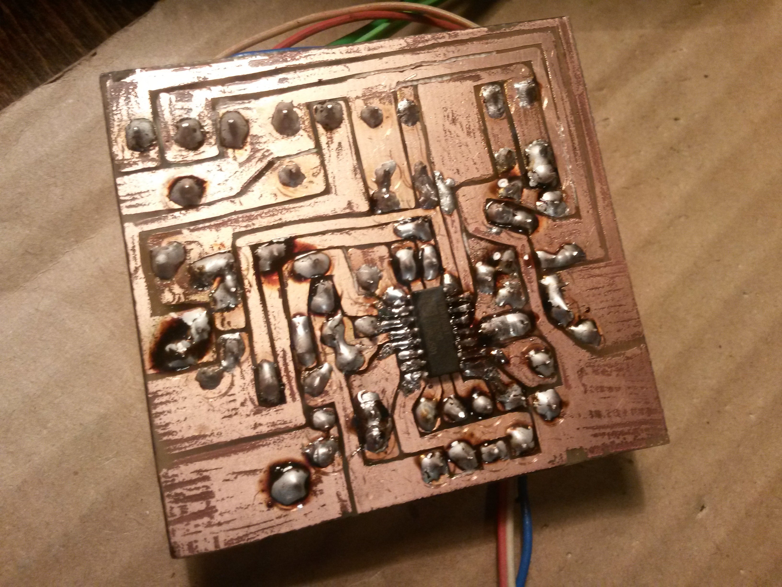
Integrated circuit TDA7088T forms the heart of this receiver. Unfortunately, it is only made in SMD package, thus special care is required while soldering. Power can be supplied by two AA cells, or from a stabilized 3.3 V supply. Peak current is only around 10 mA.
On the positive side, the receiver contains only two inductors, and both can be easily made at home. Both inductors are coreless, from 0.5 mm Cu enameled wire, wound on a 3 mm diameter. For example, a lead from a pen has exactly this diameter and I used it to wind my inductors. The inductor near varicap has 9 turns, the other one 7 turns. The one near varicap is used to seat the receiver in the 88 - 108 MHz band (it is good to use another receiver to find out what the first and last station is). This initial tuning is performed by stretching and retracting the inductor.
Varicap should be KB105Z (or BB105). I couldn't get my hands on one, but I had plenty varicaps from old TVs and receivers. I found out that the varicaps that measure 20 pF on AVR component tester, work best. They have a turquoise strip on the bottom, or a white dot on the top.
Output is only mono, and if we want stereo, we must connect a stereo decoder. There are many schematics and guides on the internet, one is also in the same issue of Amatérske rádio magazine, as this FM receiver. The mono output contains everything that is needed, including RDS information which can be also decoded. I have tried it and it works very well, but it's not what this article is about.
A speaker cannot be connected directly to the output, only headphones can be used. If we want to listen via a speaker, an audio amplifier must be connected. A simple LM386-based amplifier will also do the job. But beware - a 10M capacitor must be connected between the receiver and the amplifier - "plus" side facing the receiver and "minus" facing the amplifier. If the receiver and amplifier are connected to the same power supply, we use only the output connected to collector of KC238 transistor as the output, the second output (connected to 3V3) will stay unconnected. See the schematic below (click to enlarge).

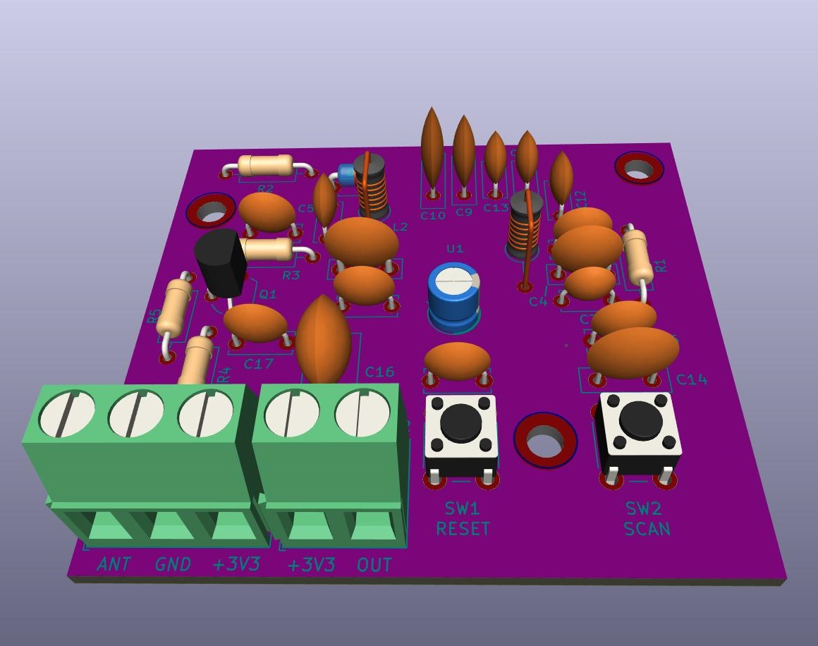
The download package contains KiCad project (a state-of-the-art free EE CAD software) and board layout is also included. I reworked it from scratch on purpose, because the original layout published in the magazine was too small with miniature components and thin copper lines, and it was very difficult to use. And I wanted to use terminal blocks for interconnections, as they make manipulation much easier. If you use my board layout, you can use ordinary THT components. It's tested and 100% working.
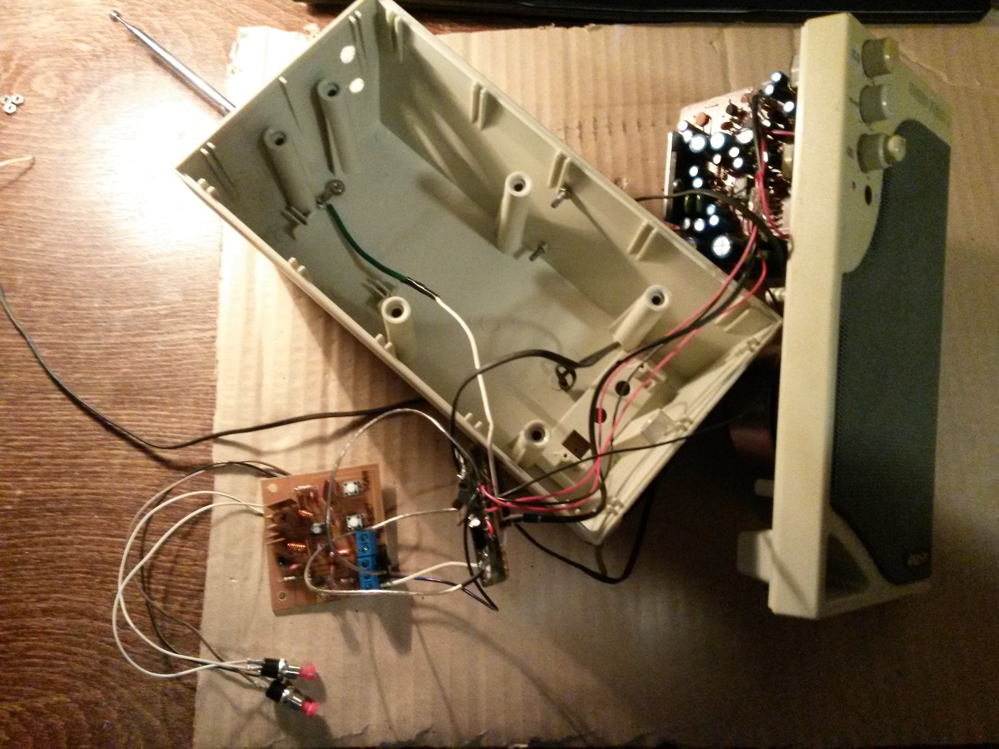
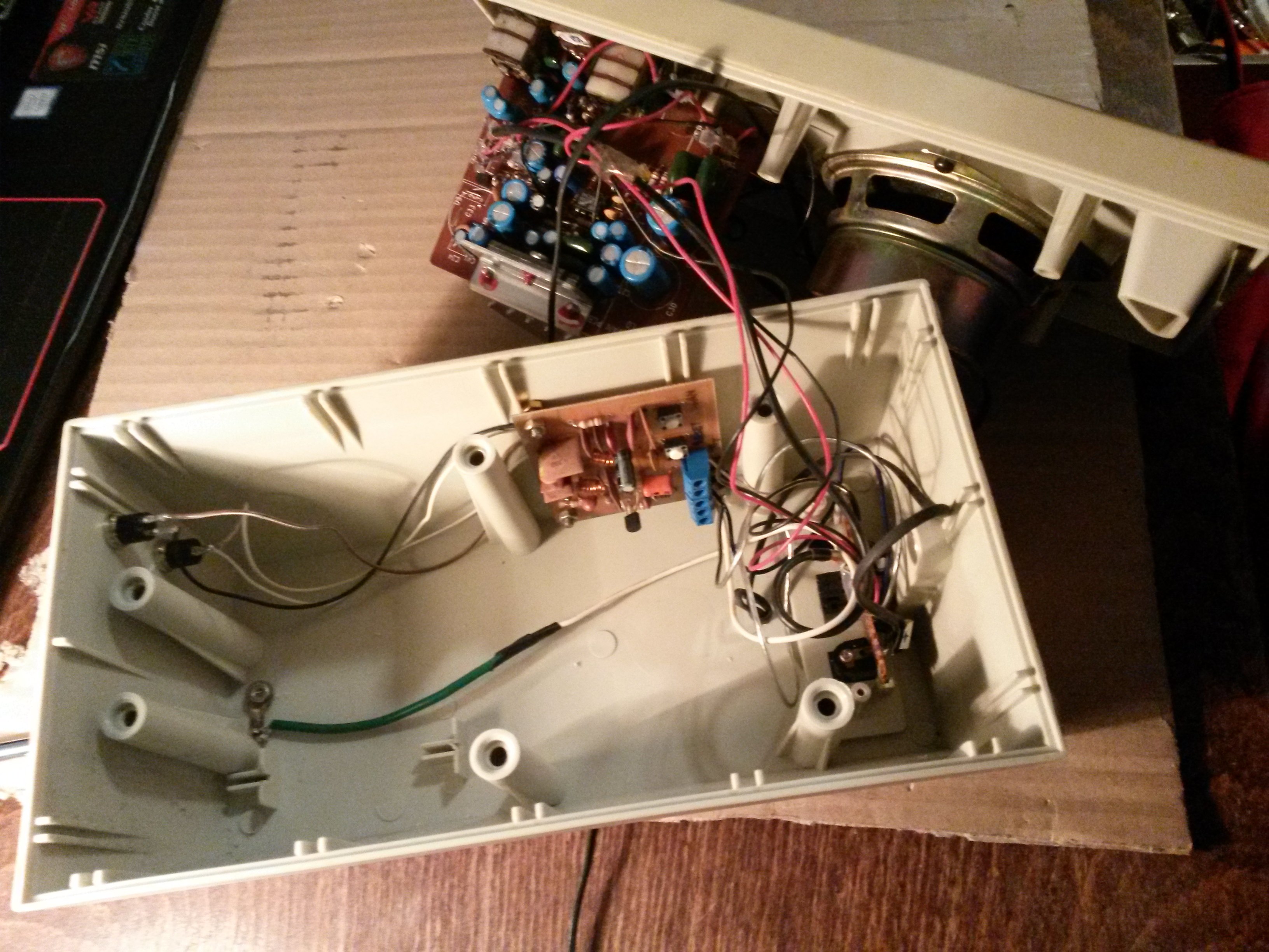
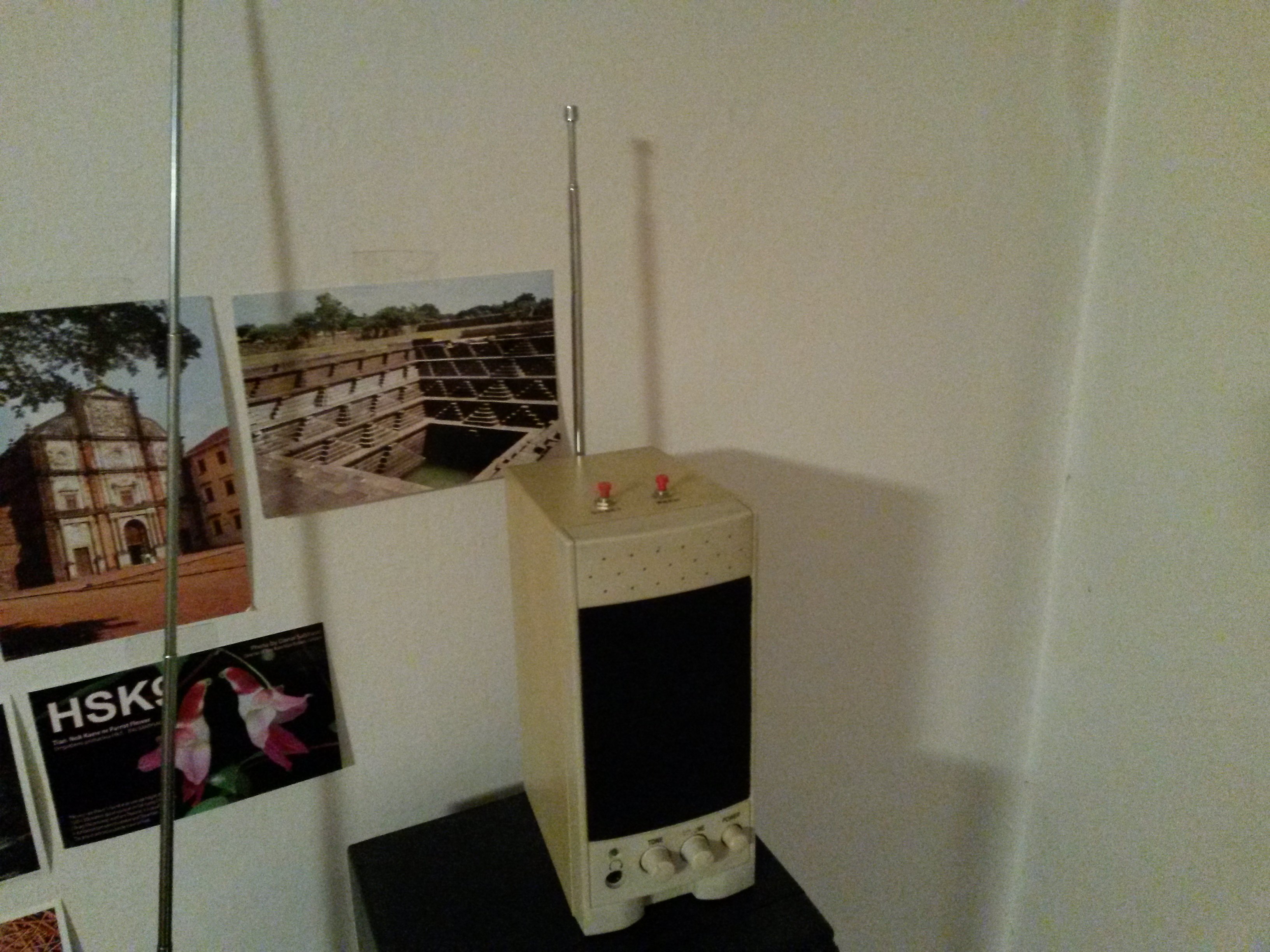
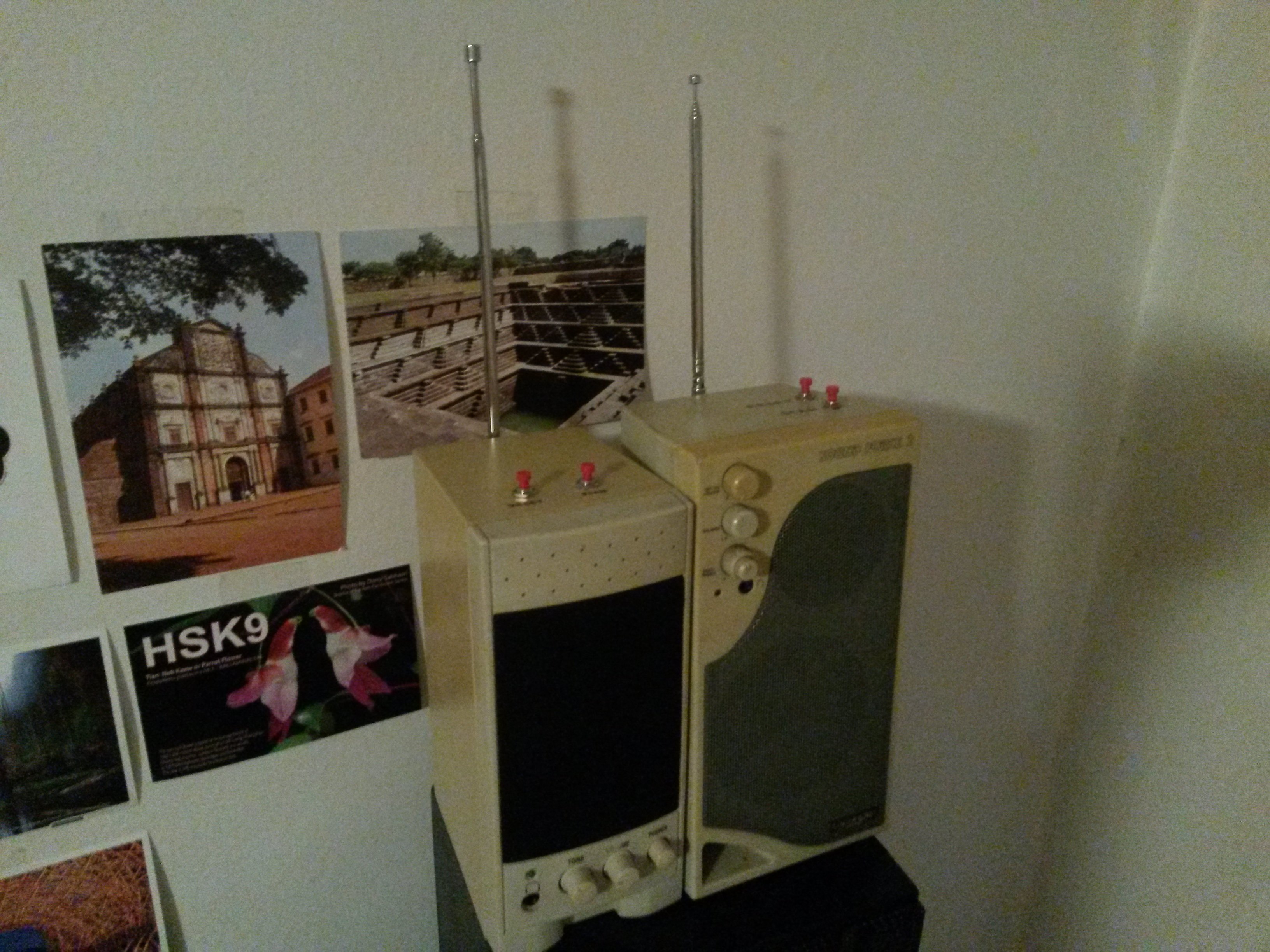
The receiver itself is so small and simple that it can be built into other devices, such as small PC speakers. I had two such speakers, one different than the other. Both were originally stereo, but I got only one from each. Fortunately, they had mains transformer and audio amplifier board inside. So all I did was drilling a few holes, attaching a telescopic antenna, two buttons to control the receiver, finding out where to mount the receiver board inside the speaker box, and connecting everything up. My final result can be seen in the photos below. All is playing well and to my full satisfaction :)