DIY Digital clock with AVR ATmega8
Experiments with AVR Atmel ATmega8 led me to an idea of building my own DIY digital clock. I had more 7-segment displays laying around so why not try something with them.
There are many guides and tutorials to creating a clock to choose from. I found some easy clock on page daqq.eu and the schematic and program seemed simple enough to me. The only problem was with the crystal because it required a special frequency and I didn't have it. However, I had many other crystals so I began studying if any of them could be used instead. I found out that it's not so simple and the frequency of crystal has its meaning. This page describes TIMERs in AVR for beginners and it was very useful for my learning.
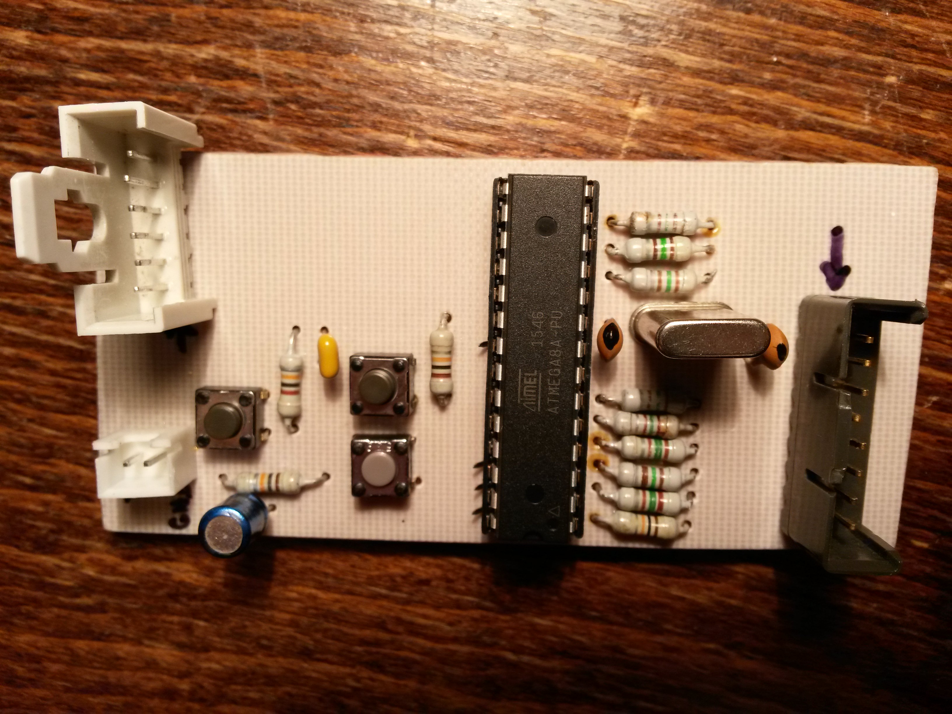
I have customized the original schematic for 6 displays (seconds are a must), drastically edited C program and reworked clock setup with 3 buttons to speed up the clock.
For brevity, these are key points of this project:
- 4,194304 MHz crystal
- 24-hour time format
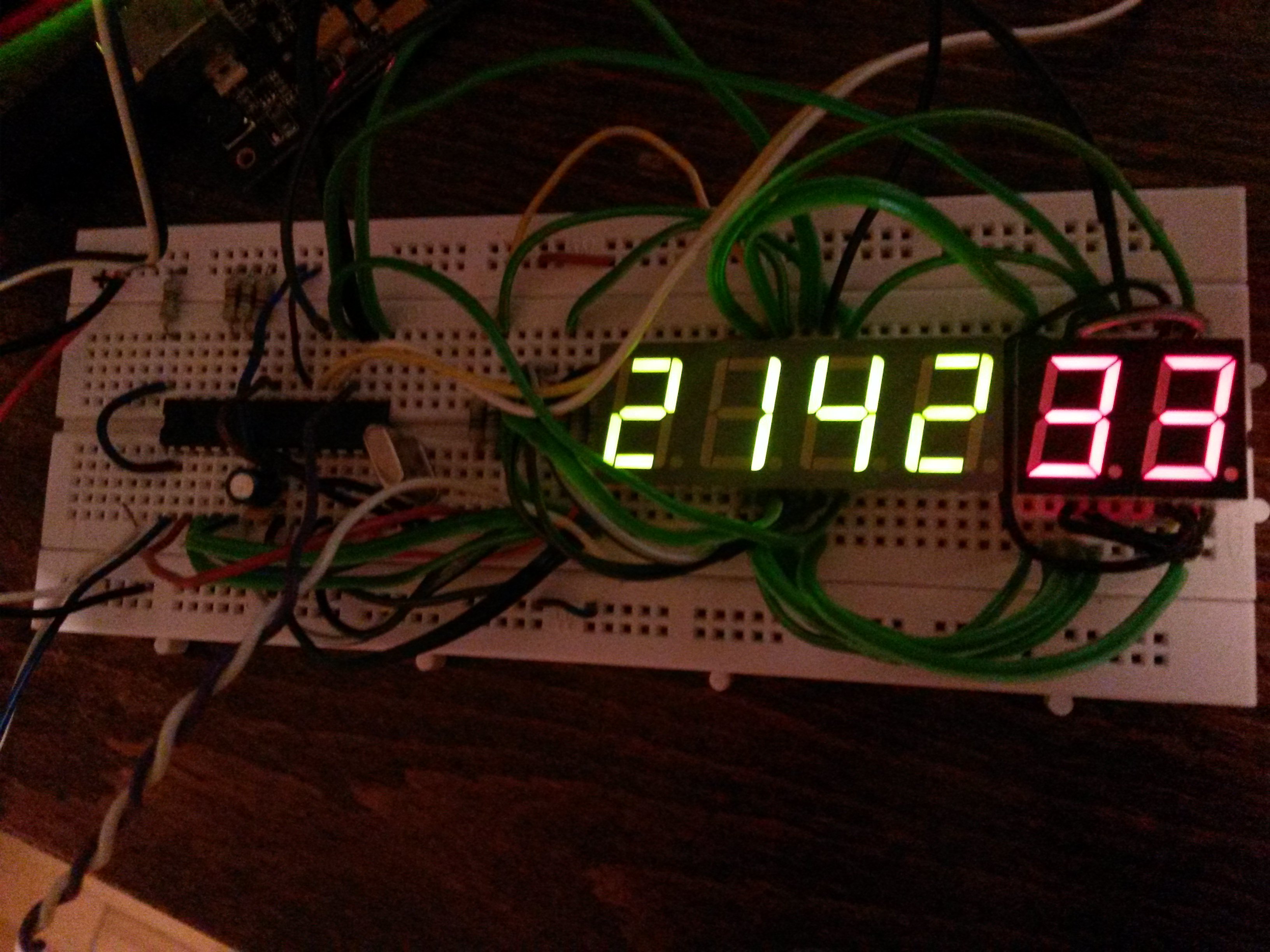
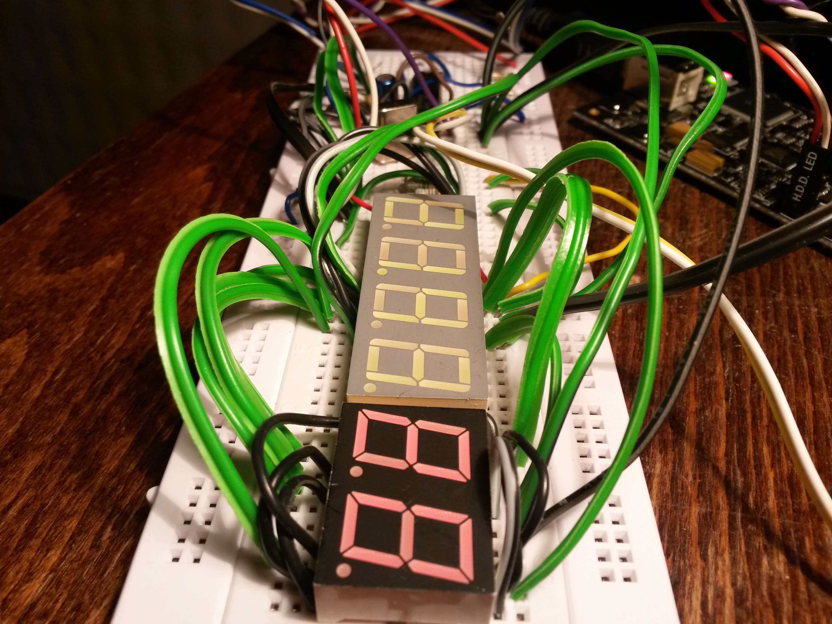
- 6 seven-segment displays with dots (multiplexed), displays are with common anode
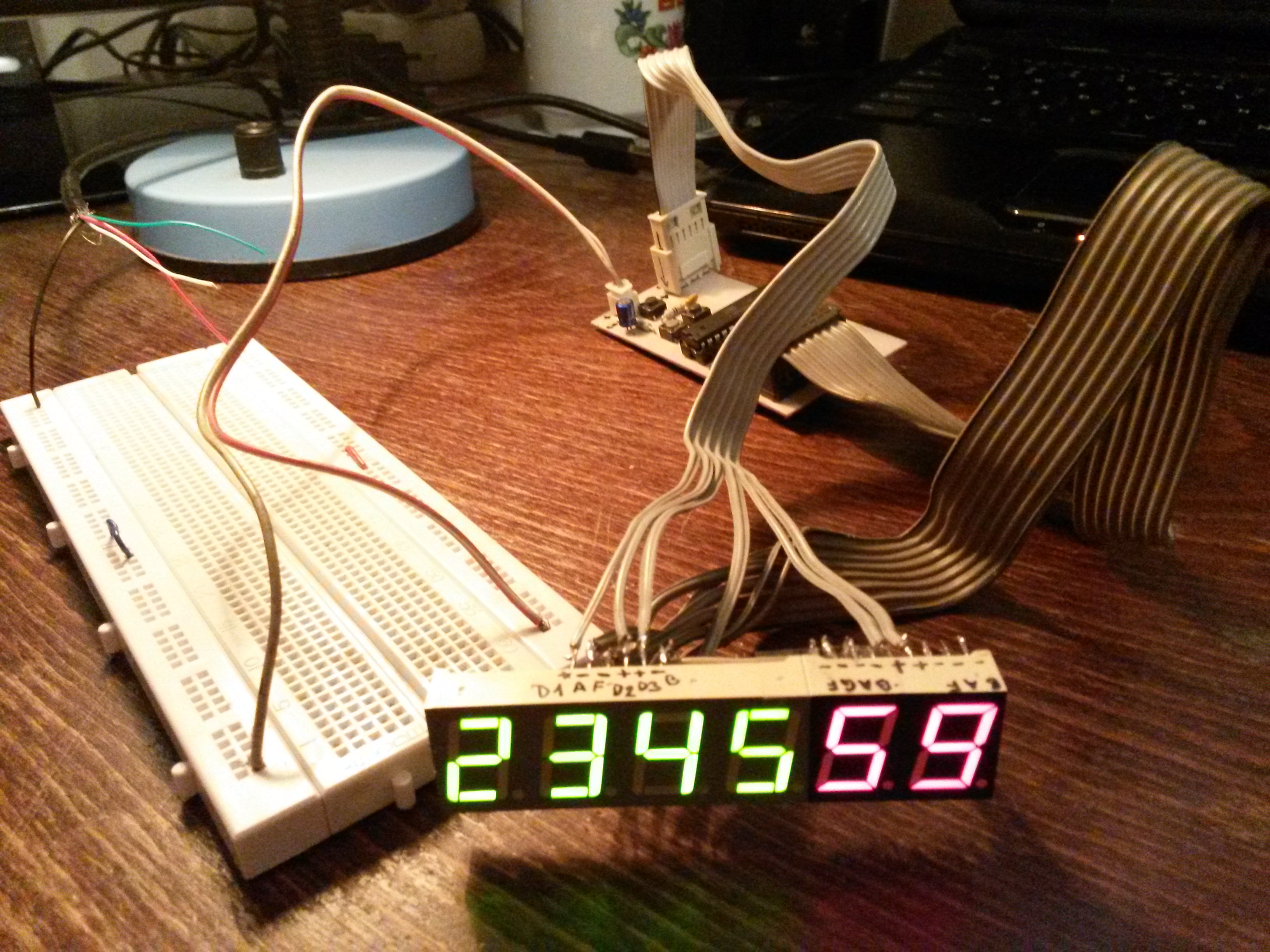
- HH:MM:SS format
- clock setup using 3 buttons which influence clock speed
- 5V DC supply required
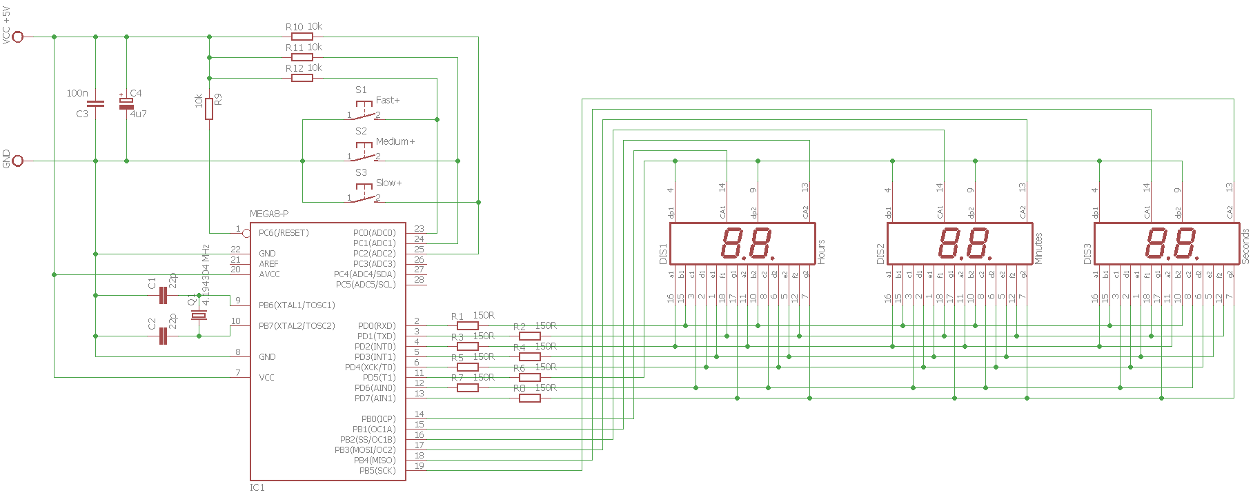
This is the schematic:
And program with comments:
#include "hw.h"
#include <avr/io.h>
#include <avr/interrupt.h>
#include<stdio.h>
// BTNx is 1 if respective button is pressed TIMER1_COMPA interrupt once per second
#define BTN0() (bit_is_clear(PINC, 0))
#define BTN1() (bit_is_clear(PINC, 1))
#define BTN2() (bit_is_clear(PINC, 2))
// default TIMER1 compare value to get
#define DEFAULT_OCR1A 16383
volatile unsigned char sec1 = 0;
volatile unsigned char sec10 = 0;
volatile unsigned char min1 = 0;
volatile unsigned char min10 = 0;
volatile unsigned char hour1 = 0;
volatile unsigned char hour10 = 0;
volatile unsigned char activeseg = 0; // indicates active display segment (used for multiplexing)
// display segments configuration
#define _s_A 2
#define _s_B 0
#define _s_C 6
#define _s_D 4
#define _s_E 3
#define _s_F 1
#define _s_G 7
#define _s_dot 5
const unsigned char segs[] =
{
_BV(_s_A) | _BV(_s_B) | _BV(_s_C) | _BV(_s_D) | _BV(_s_E) | _BV(_s_F), //0
_BV(_s_B) | _BV(_s_C), //1
_BV(_s_A) | _BV(_s_B) | _BV(_s_D) | _BV(_s_E) | _BV(_s_G), //2
_BV(_s_A) | _BV(_s_B) | _BV(_s_C) | _BV(_s_D) | _BV(_s_G), //3
_BV(_s_B) | _BV(_s_C) | _BV(_s_F) | _BV(_s_G), //4
_BV(_s_A) | _BV(_s_C) | _BV(_s_D) | _BV(_s_F) | _BV(_s_G), //5
_BV(_s_A) | _BV(_s_C) | _BV(_s_D) | _BV(_s_E) | _BV(_s_F) | _BV(_s_G), //6
_BV(_s_A) | _BV(_s_B) | _BV(_s_C), //7
_BV(_s_A) | _BV(_s_B) | _BV(_s_C) | _BV(_s_D) | _BV(_s_E) | _BV(_s_F) | _BV(_s_G),//8
_BV(_s_A) | _BV(_s_B) | _BV(_s_C) | _BV(_s_D) | _BV(_s_F) | _BV(_s_G),//9
_BV(_s_A) | _BV(_s_B) | _BV(_s_C) | _BV(_s_E) | _BV(_s_F) | _BV(_s_G), //A
_BV(_s_C) | _BV(_s_D) | _BV(_s_E) | _BV(_s_F) | _BV(_s_G), //B
_BV(_s_A) | _BV(_s_D) | _BV(_s_E) | _BV(_s_F), //C
_BV(_s_B) | _BV(_s_C) | _BV(_s_D) | _BV(_s_E) | _BV(_s_G), //D
_BV(_s_A) | _BV(_s_D) | _BV(_s_E) | _BV(_s_F) | _BV(_s_G), //E
_BV(_s_A) | _BV(_s_E) | _BV(_s_F) | _BV(_s_G) //F
};
int main(void)
{
// set all PORTB and PORTD pins as output
DDRB = 0xFF;
DDRD = 0xFF;
// show empty display at the beginning
PORTB = 0xFF;
PORTD = 0xFF;
// TIMER1 configuration
TCCR1B |= _BV(WGM12); // configure timer 1 for CTC mode
TIMSK |= _BV(OCIE1A); // enable CTC interrupt
OCR1A = DEFAULT_OCR1A; // set CTC compare value
TCCR1B |= _BV(CS12); // configure prescaler to 256 and start timer
// TIMER2 configuration
TIMSK |= _BV(TOIE2); // enable overflow interrupt
TCCR2 |= _BV(CS21); // configure prescaler to 8 and start timer
sei(); // enable global interrupts
// main loop is empty, program logic is done in interrupt vectors
for (;;)
{
}
}
// ISR of interrupt that is normally called once per second
// increases internal time information by 1 second each time
ISR(TIMER1_COMPA_vect)
{
// special handling of buttons for user configuration of time
if (OCR1A == DEFAULT_OCR1A)
{
// is some of the buttons pressed?
// if yes, decrease TIMER1 compare value to make the clock go faster accordingly
// which invokes this ISR more often than once per second
if (BTN0())
{
OCR1A = DEFAULT_OCR1A / 4096; // fastest
sec1 = 0;
sec10 = 0;
}
else if (BTN1())
{
OCR1A = DEFAULT_OCR1A / 512; // medium
sec1 = 0;
sec10 = 0;
}
else if (BTN2())
{
OCR1A = DEFAULT_OCR1A / 64; // slowest
sec1 = 0;
sec10 = 0;
}
}
else if (OCR1A != DEFAULT_OCR1A && !BTN0() && !BTN1() && !BTN2())
{
// if previously some of the buttons were pressed and now they are not
// (TIMER1 compare value is different from default)
// return TIMER11 compare value to default to make the clock go normally again
OCR1A = DEFAULT_OCR1A;
}
sec1++;
if (sec1 > 9)
{
sec10++;
sec1 = 0;
}
if (sec10 > 5)
{
min1++;
sec10 = 0;
}
if (min1 > 9)
{
min10++;
min1 = 0;
}
if (min10 > 5)
{
hour1++;
min10 = 0;
}
if (hour1 > 9)
{
hour10++;
hour1 = 0;
}
if (hour10 == 2 && hour1 == 4)
{
hour1 = 0;
hour10 = 0;
}
}
// display multiplexing is done in this ISR
// it is called often enough per second for display blinking to be invisible
ISR(TIMER2_OVF_vect)
{
if (activeseg == 5)
{
activeseg = 0;
} else {
activeseg++;
}
switch (activeseg)
{
case 0:
PORTD = ~segs[hour10];
PORTB = 1;
break;
case 1:
PORTD = ~segs[hour1];
PORTB = 2;
// blinking dot after 2nd segment
if ((sec1 & 1) == 0)
{
PORTD &= ~_BV(_s_dot);
} else {
PORTD |= _BV(_s_dot);
}
break;
case 2:
PORTD = ~segs[min10];
PORTB = 4;
break;
case 3:
PORTD = ~segs[min1];
PORTB = 8;
// blinking dot after 4th segment
if ((sec1 & 1) == 0)
{
PORTD &= ~_BV(_s_dot);
} else {
PORTD |= _BV(_s_dot);
}
break;
case 4:
PORTD = ~segs[sec10];
PORTB = 16;
break;
case 5:
PORTD = ~segs[sec1];
PORTB = 32;
break;
}
}
When flashing the software, FUSES need to be set this way:
- HIGH 0xD9
- LOW 0xED
- SUT_CKSEL: Ext. Crystal/Resonator Medium Freq. Start-up time: 16K CK + 4 ms (this is part of LOW fuses setting)
Download package contains program in HEX file, source code (solution for Atmel Studio), schematic and partlist.
If you decide to build this clock and run into issues, drop me a line and I will help if I can.